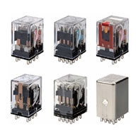
MY
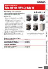
General-purpose relays family suitable for different environments and applications
- MY family products has standard features on all models* like transparent cover, mechanical indicator to easily check the contacts status and the LED not only to indicate the correct operation of the relay, but also to immediate identify the coil voltage type: red LED for AC coil and green LED for DC coil
- 2.6 mm wide pins which offer a higher conductivity and less temperature increase
- MY-GS-R is the star of the family with 2 and 4 poles models available with LED, test button and protection. The DC version thanks to the LED design has no polarity (models with diode excluded)
- Available hermetically or plastic sealed relays, models with bifurcated au cladded contacts for minute loads
- Wiring work can be shortened by as much as 60%** compared to conventional screw terminal sockets. Combining the MY with the Push-in Plus terminal sockets (PYF-[]-PU) the light insertion force permits to reduce the wiring time
* Special models are excluded
** When both push-in plus terminals and screw terminal sockets are combined with plug-in terminal types
Product discontinuation: March 2024 is applicable ONLY for EUROPE. Please download this discontinuation notice for further information.
Specifications & ordering info
| Product | Mounting method | Usage | Poles | Rated carry current | Coil voltage | Operation voltage | Contact material | Contact description | Features | Terminal type | Description | |
|---|---|---|---|---|---|---|---|---|---|---|---|---|
|
|
With plug-in socket | General purpose | 2 | 10 A | 110 V | AC | Ag | DPDT | Transparent case, With mechanical indicator | Plug-in, Solder | Relay, plug-in, 8-pin, DPDT, 10 A, mechanical indicator, 110/120 VAC (20260521) |
|
|
|
With plug-in socket | General purpose | 2 | 10 A | 12 V | AC | Ag | DPDT | Transparent case, With mechanical indicator | Plug-in, Solder | Relay, plug-in, 8-pin, DPDT, 10 A, mechanical indicator, 12 VAC.... |
|
|
|
With plug-in socket | General purpose | 2 | 10 A | 230 V | AC | Ag | DPDT | Transparent case, With mechanical indicator | Plug-in, Solder | Relay, plug-in, 8-pin, DPDT, 10 A, mechanical indicator, 220/240 VAC |
|
|
|
With plug-in socket | General purpose | 2 | 10 A | 24 V | AC | Ag | DPDT | Transparent case, With mechanical indicator | Plug-in, Solder | Relay, plug-in, 8-pin, DPDT, 10 A, mechanical indicator, 24 VAC |
|
|
|
With plug-in socket | General purpose | 2 | 10 A | 48 V | AC | Ag | DPDT | Transparent case, With mechanical indicator | Plug-in, Solder | Relay, plug-in, 8-pin, DPDT, 10 A, mechanical indicator, 48 VAC |
|
|
|
With plug-in socket | General purpose | 2 | 10 A | 110 V | DC | Ag | DPDT | Transparent case, With mechanical indicator | Plug-in, Solder | Relay, plug-in, 8-pin, DPDT, 10 A, mechanical indicator, 100/110 VDC |
|
|
|
With plug-in socket | General purpose | 2 | 10 A | 12 V | DC | Ag | DPDT | Transparent case, With mechanical indicator | Plug-in, Solder | Relay, plug-in, 8-pin, DPDT, 10 A, mechanical indicator, 12 VDC |
|
|
|
With plug-in socket | General purpose | 2 | 10 A | 24 V | DC | Ag | DPDT | Transparent case, With mechanical indicator | Plug-in, Solder | Relay, plug-in, 8-pin, DPDT, 10 A, mechanical indicator, 24 VDC |
|
|
|
With plug-in socket | General purpose | 2 | 10 A | 48 V | DC | Ag | DPDT | Transparent case, With mechanical indicator | Plug-in, Solder | Relay, plug-in, 8-pin, DPDT, 10 A, mechanical indicator, 48 VDC |
|
|
|
With plug-in socket | General purpose | 2 | 10 A | 110 V | AC | Ag | DPDT | CR circuit, LED, Test button, Transparent case, With mechanical indicator | Plug-in, Solder | Relay, plug-in, 8-pin, DPDT, 10 A, mechanical & LED indicators, Coil Surge Absorption, lockable push test button, 110/120 VAC |
|
|
|
With plug-in socket | General purpose | 2 | 10 A | 230 V | AC | Ag | DPDT | CR circuit, LED, Test button, Transparent case, With mechanical indicator | Plug-in, Solder | Relay, plug-in, 8-pin, DPDT, 10 A, mechanical & LED indicators, Coil Surge Absorption, lockable push test button, 220/240 VAC |
|
|
|
With plug-in socket | General purpose | 2 | 10 A | 24 V | DC | Ag | DPDT | Diode, LED, Test button, Transparent case, With mechanical indicator | Plug-in | Relay, plug-in, 8-pin, DPDT, 10 A, mechanical & LED indicators, with built-in diode for coil surge absorption, reverse polarity, lockable push test button, 24 VDC |
|
|
|
With plug-in socket | General purpose | 2 | 10 A | 110 V | DC | Ag | DPDT | Diode, LED, Test button, Transparent case, With mechanical indicator | Plug-in, Solder | Relay, plug-in, 8-pin, DPDT, 10 A, mechanical & LED indicators, Coil Surge Absorption, lockable push test button, 100/110 VDC |
|
|
|
With plug-in socket | General purpose | 2 | 10 A | 12 V | DC | Ag | DPDT | Diode, LED, Test button, Transparent case, With mechanical indicator | Plug-in, Solder | Relay, plug-in, 8-pin, DPDT, 10 A, mechanical & LED indicators, Coil Surge Absorption, lockable push test button, 12 VDC |
|
|
|
With plug-in socket | General purpose | 2 | 10 A | 24 V | DC | Ag | DPDT | Diode, LED, Test button, Transparent case, With mechanical indicator | Plug-in, Solder | Relay, plug-in, 8-pin, DPDT, 10 A, mechanical & LED indicators, Coil Surge Absorption, lockable push test button, 24 VDC |
|
|
|
With plug-in socket | General purpose | 2 | 10 A | 110 V | AC | Ag | DPDT | LED, Test button, Transparent case, With mechanical indicator | Plug-in, Solder | Relay, plug-in, 8-pin, DPDT, 10 A, mechanical & LED indicators, lockable push test button, 110/120 VAC |
|
|
|
With plug-in socket | General purpose | 2 | 10 A | 12 V | AC | Ag | DPDT | LED, Test button, Transparent case, With mechanical indicator | Plug-in, Solder | Relay, plug-in, 8-pin, DPDT, 10 A, mechanical & LED indicators, lockable push test button, 12 VAC |
|
|
|
With plug-in socket | General purpose | 2 | 10 A | 230 V | AC | Ag | DPDT | LED, Test button, Transparent case, With mechanical indicator | Plug-in, Solder | Relay, plug-in, 8-pin, DPDT, 10 A, mechanical & LED indicators, lockable push test button, 220/240 VAC |
|
|
|
With plug-in socket | General purpose | 2 | 10 A | 24 V | AC | Ag | DPDT | LED, Test button, Transparent case, With mechanical indicator | Plug-in, Solder | Relay, plug-in, 8-pin, DPDT, 10 A, mechanical & LED indicators, lockable push test button, 24 VAC |
|
|
|
With plug-in socket | General purpose | 2 | 10 A | 48 V | AC | Ag | DPDT | LED, Test button, Transparent case, With mechanical indicator | Plug-in, Solder | Relay, plug-in, 8-pin, DPDT, 10 A, mechanical & LED indicators, lockable push test button, 48 VAC |
|
Need assistance?
We’re here to help! Reach out, and our specialists will assist you in finding the best solution for your business.
Ota minuun yhteyttä MY

Kiitos yhteydenotostasi. Otamme teihin yhteyttä mahdollisimman pian.
Meillä on teknisiä ongelmia. Emme ole pystyneet vastaanottamaan lomakettasi. Pahoittelemme ja pyydämme yrittämään uudelleen myöhemmin.
Tarjous MY
Tällä lomakkeella voit pyytää tarjouksen valitsemastasi tuotteesta. Täytäthän kaikki *-merkityt kentät. Henkilökohtaisia tietojasi käsitellään luottamuksellisesti.
Kiitos tarjouspyynnöstä. Toimitamme tarvittavat tiedot teille mahdollisimman pian.
Meillä on teknisiä ongelmia. Emme ole pystyneet vastaanottamaan lomakettasi. Pahoittelemme ja pyydämme yrittämään uudelleen myöhemmin.
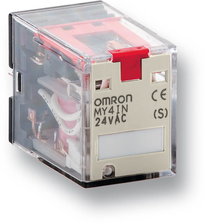
Models
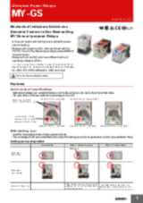
MY-GS-R - The star of MY family relays
- MY-GS-R the last addition to MY family: produced by a complete automated factory
- Models with LED has no polarity for the DC coil specification without diode
- The printing on the coil tape indicates the operating coil specification
- Mechanical operation indicators are a standard feature on all models
- RoHS complaint, UL, CSA, and IEC (VDE certification).
- Mechanical indicators are a standard feature on all models to easily check the contact status.
- MY-GS-R is suitable for application which need a reliable relay, the standard model is frequently seen in HVAC industry or packaging machine for the food and beverage industry
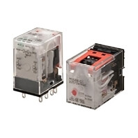
MY(S) - Miniature Power Relays
Versatile plug-in relay that sets the standard
- Bifurcated contacts are available to achieve reliable low current switching during the entire electrical life. Full range of sockets covering mounting by screw, box clamp and screw-less clamp method.
- MY-S is available in the 3 pole version
- The bifurcated contact are au cladded perfect for minute loads
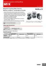
MYK - Miniature Power Latching Relays
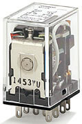
Magnetic latching relay ideal for memory- and data-transmission circuits
- MYK Magnetic latching relays that retains contact operation status and with low power consumption
- Double-winding latch system that holds residual magnetism. The special magnetic materials make changes due to aging negligible, thus ensuring long continuous holding time. There is little change in characteristics such as contact follow, contact pressure, etc. throughout its long life.
- Excellent vibration/shock resistance
- Built-in operation indicator ensures easy ON/OFF operation monitoring
- MY2K is also used in panels dedicated to Wind Energy Application
MYQ/MYH - Miniature Power Sealed Relays
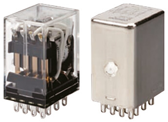
Sealed relays that are tough in environments where dust or corrosive gases, etc., are present
- In dust-producing environments such as where molding machines and grinders are present and in application environments in which small insects (such as gnat or mosquitos) are present, these foreign substances can penetrate into the relay, through gaps between parts of the relay and the relay's ventilation holes. Once inside the relay, dust and insects often remain inside. If they adhere to the contacts, the result can be problems such as contact failure and unstable contacts.Plastic sealed relays (MYQ) and hermetically sealed relays (MYH) are resistant to effects from the surrounding environment
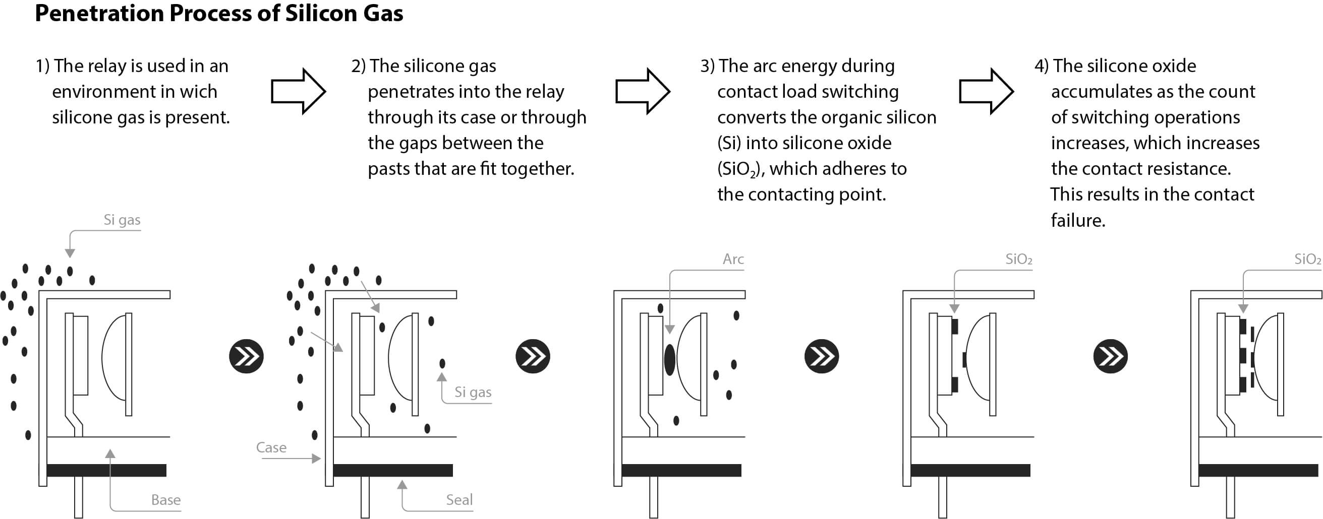
- Suggested also for environments where corrosive gases such as chloride gas, sulfuric gas, and silicone gas are generated
- They are also resistant to environments where salt damage is occurred and where dust is generated.
- Prevent relay contact failures via a highly airtight structure
Videos

-

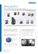
OMRON Relay Quality
Creating the perfect relays may seem like a straightforward task, but it’s a complex process that requires the most advanced manufacturing processes. This ensures that every component inside our relays are precisely assembled and protected from any outside contaminants. Ignoring this crucial step could jeopardize the reliability of the relays and compromise their switching activity. At times, machines can experience unplanned downtime, with the causes remaining elusive, in many cases restarting the machine or replacing the relays resolves the issue. OMRON determined that such incidents are primarily caused by inadequate contact conduction, which frequently results from dust caught between the contacts during manufacturing. OMRON's unique production techniques avoid poor conduction due to dust by providing standardized product design, producing the products in clean room with strict entry/exit control rules, and utilizing OMRON’s unique dust removal technology. This production technique are applied for all the OMRON relays especially the new ones introduced in the line up G2RV-ST/G3RV-ST, and MY-GS-R. Find out more about our new relays in our website: #MakeitOMRON #MakeitExcellent
02:30
OMRON Relay Quality
Creating the perfect relays may seem like a straightforward task, but it’s a complex process that requires the most advanced manufacturing processes. This ensures that every component inside our relays are precisely assembled and protected from any outside contaminants. Ignoring this crucial step could jeopardize the reliability of the relays and compromise their switching activity. At times, machines can experience unplanned downtime, with the causes remaining elusive, in many cases restarting the machine or replacing the relays resolves the issue. OMRON determined that such incidents are primarily caused by inadequate contact conduction, which frequently results from dust caught between the contacts during manufacturing. OMRON's unique production techniques avoid poor conduction due to dust by providing standardized product design, producing the products in clean room with strict entry/exit control rules, and utilizing OMRON’s unique dust removal technology. This production technique are applied for all the OMRON relays especially the new ones introduced in the line up G2RV-ST/G3RV-ST, and MY-GS-R. Find out more about our new relays in our website: #MakeitOMRON #MakeitExcellentRelated products
-
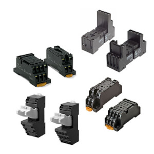
PYF is the MY relays family sockets range, also suitable for solid state relays (SSR) and timers
Downloads
_miniature_power_relays_datasheet_en.jpg)
_series_(europe)_discontinuation_notice_en.jpg)
_discontinuation_notice_en.jpg)
_myk_myq_myh_miniature_power_relays_datasheet_en.jpg)
n1-d2_and_my4(i)n1-d2_discontinuation_notice_en.jpg)